
Latest Blog
Blog
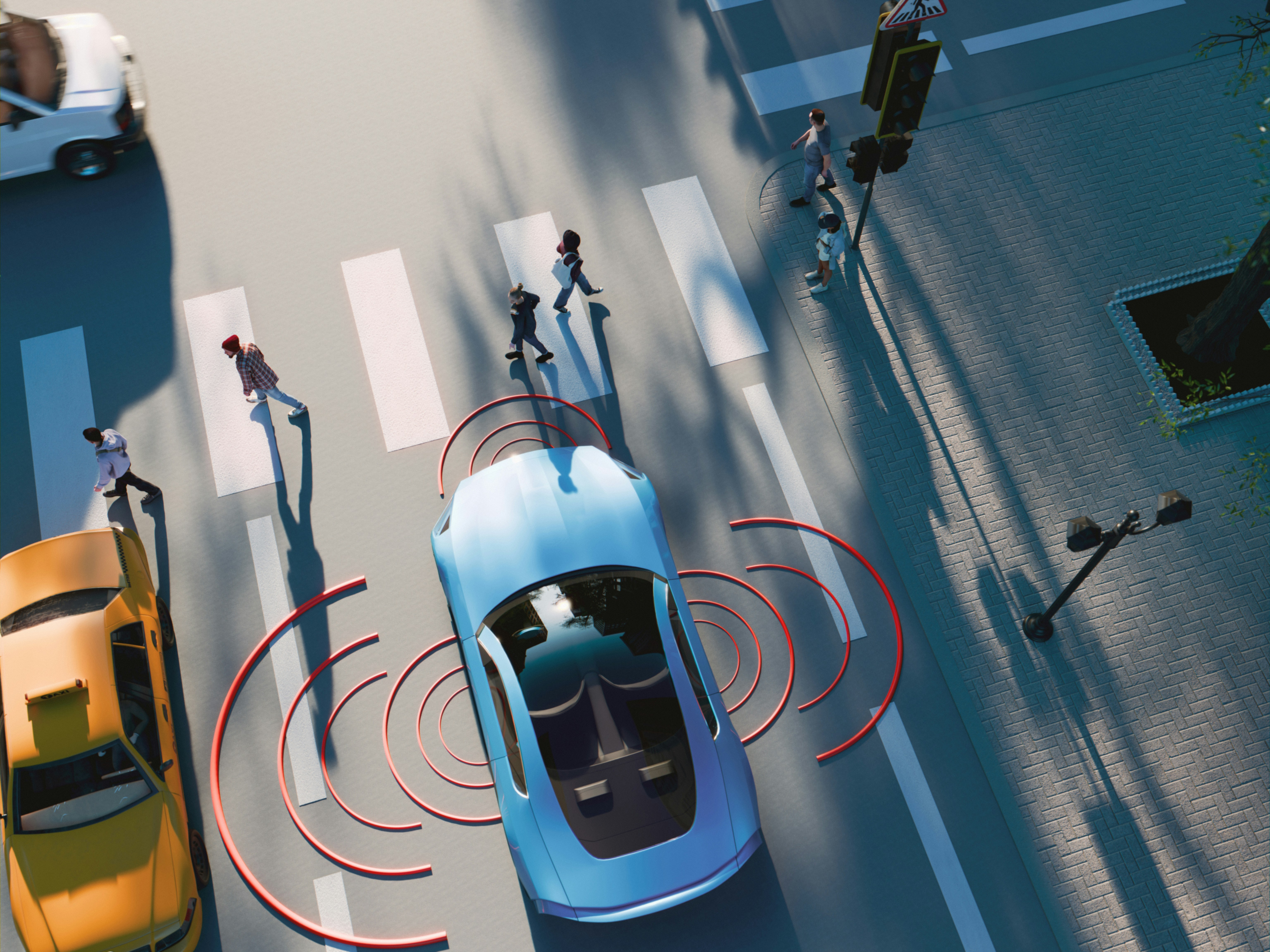
From Optics to Legislation, Optikos is Establishing the Standard for Thermal Camera Safety in Autonomous Vehicles

Daniela Dandes
Jun 05, 2026

Latest Blog
Blog
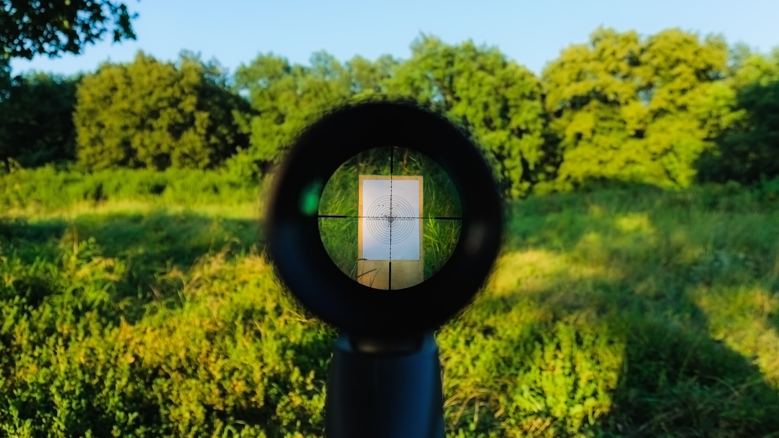
That Extra Monte Carlo Tolerance Analysis Just Might Save Your Next Defense Project
Daniela Dandes
May 12, 2026
Latest Blog
Blog
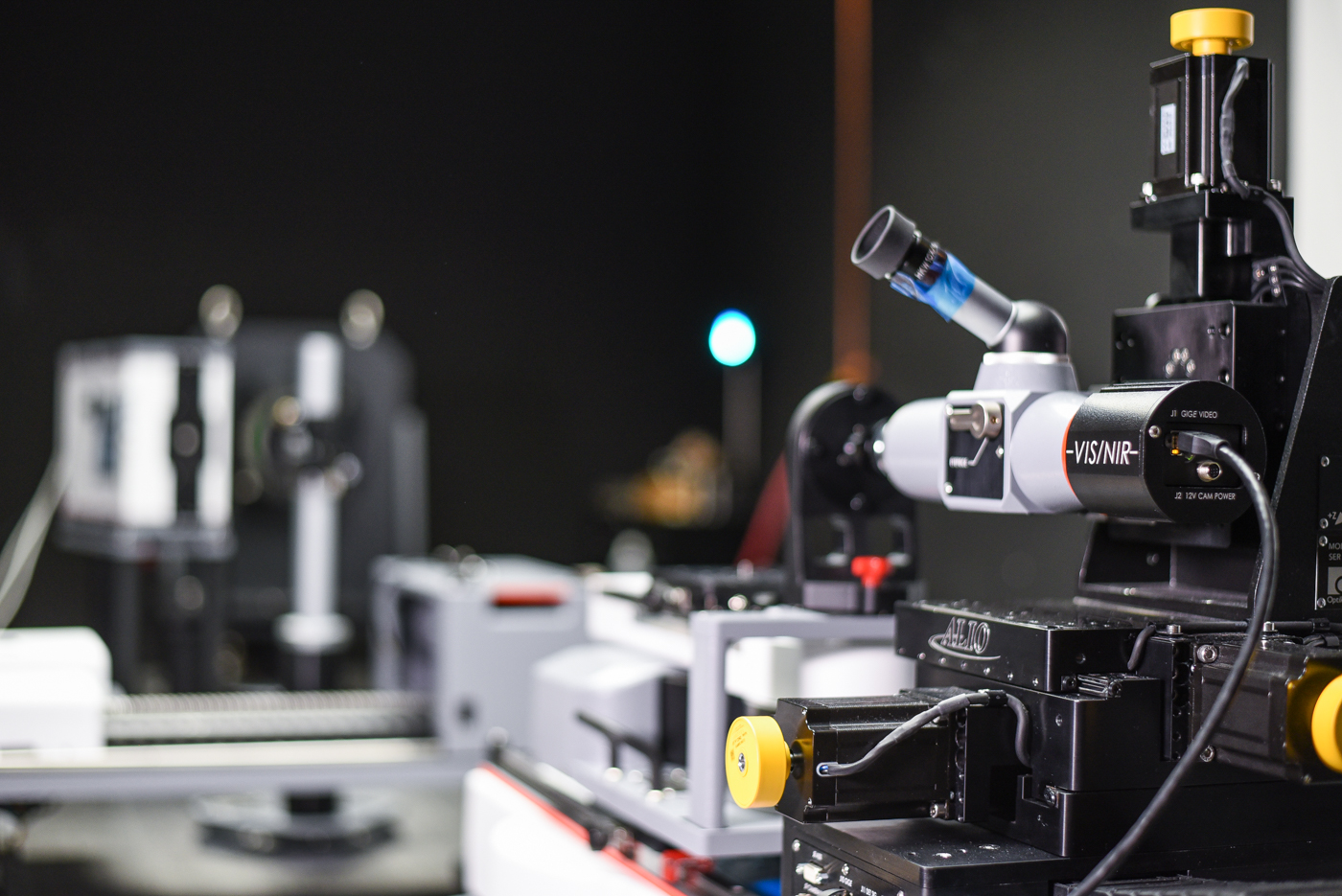
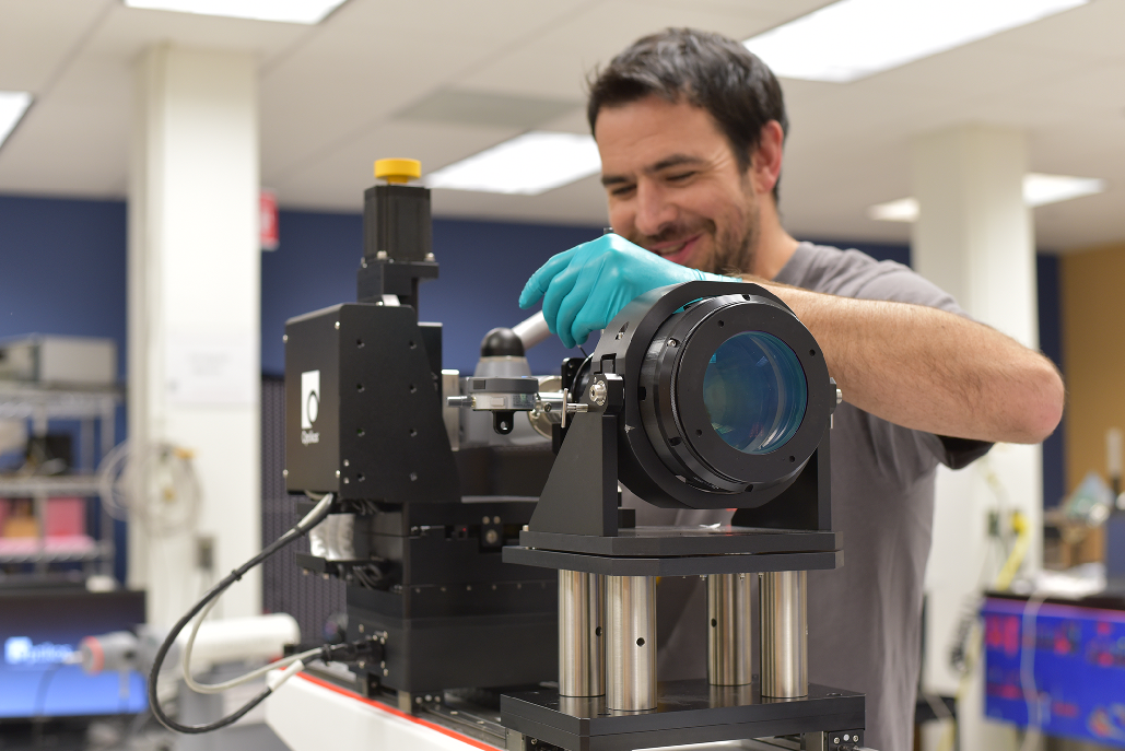
The OpTest® Bench: A Lens Metrology Multitool For The Defense Industry

Hillary Balonek
May 07, 2026
Latest Blog
Blog
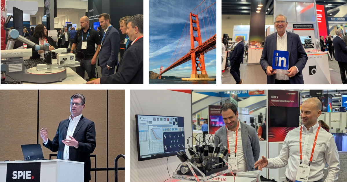
Defense Upgrades Call for the Best Optical Systems at the 2026 SPIE Defense + Security
Daniela Dandes
Apr 17, 2026
Latest Blog
Blog
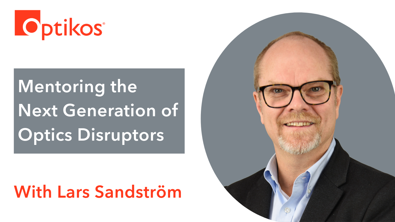
Mentoring the Next Generation of Optics Disruptors with Lars Sandström
Daniela Dandes
Apr 02, 2026

Latest Blog
Blog
Non-Negotiables for Space: Testing Optics via Vacuum-Compatible Metrology Solutions
Daniela Dandes
Mar 26, 2026
Blog
From Optics to Legislation, Optikos is Establishing the Standard for Thermal Camera Safety in Autonomous Vehicles
06/05/2026
Blog
That Extra Monte Carlo Tolerance Analysis Just Might Save Your Next Defense Project
05/12/2026
Blog
The OpTest® Bench: A Lens Metrology Multitool For The Defense Industry
05/07/2026
Blog
Defense Upgrades Call for the Best Optical Systems at the 2026 SPIE Defense + Security
04/17/2026
Blog
Mentoring the Next Generation of Optics Disruptors with Lars Sandström
04/02/2026
Blog
Non-Negotiables for Space: Testing Optics via Vacuum-Compatible Metrology Solutions
03/26/2026
Blog
Rising to the Challenge in 2026 at Optikos
02/20/2026
Blog
The Photonics Industry Is Growing Up: Our Take on Photonics West 2026
02/05/2026
Blog
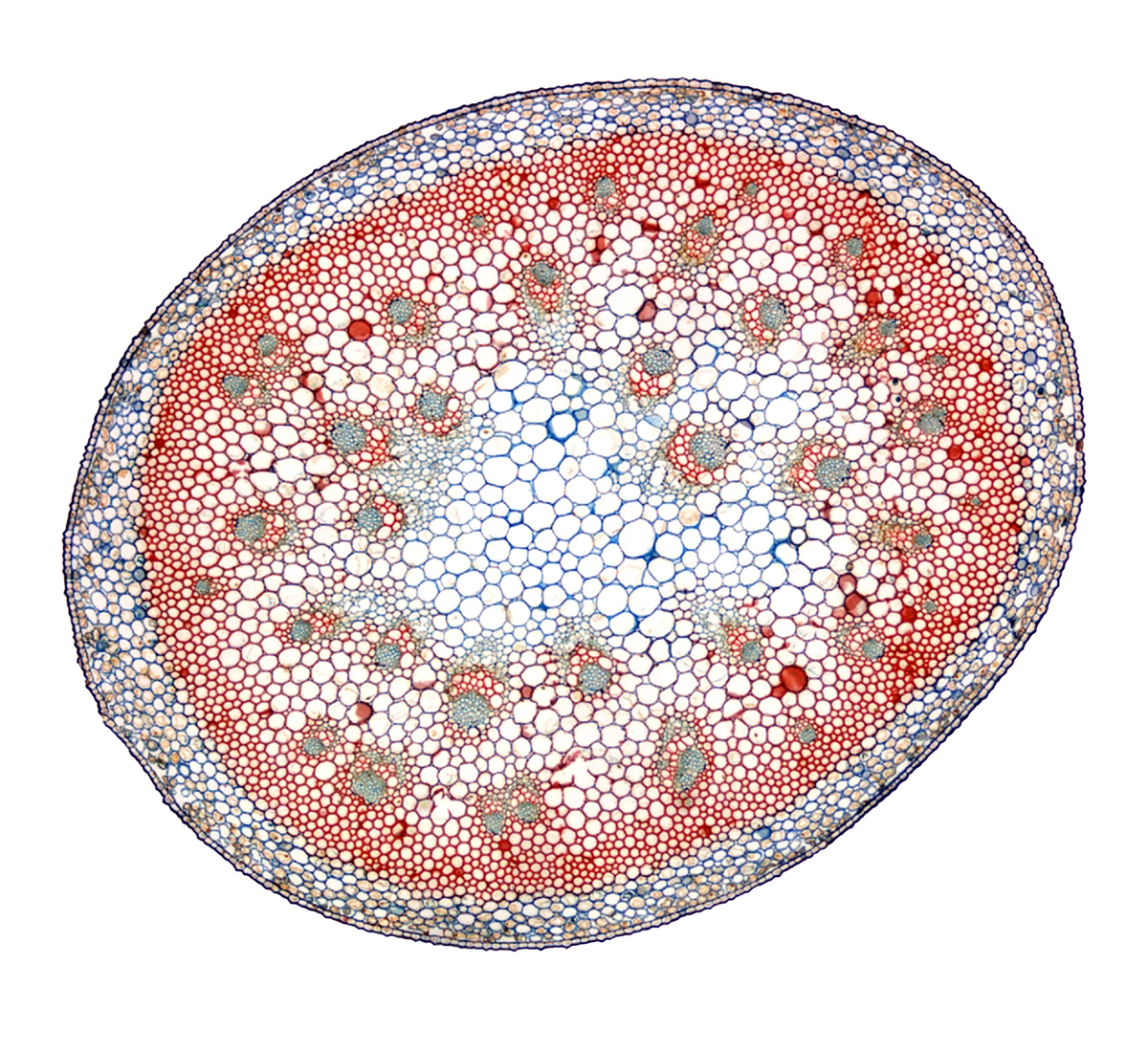
Understanding the Design-to-Testing Gap in Biomedical Optical Systems at Photonics West 2026
01/15/2026