Encircled energy (EE) is an important metric for characterization of optical systems designed for light collection. These applications typically use an image-forming lens where the amount of energy collected on a detector is more important than the resolution or MTF of the imaging system. An example is range-finding. An emitted laser pulse is reimaged onto a detector by a lens. Long distance range is directly related to how much of the imaged spot lands within the area of the detecting photodiode (or other detecting element). Encircled energy is an effective metric to characterize this collection efficiency.
Often Encircled energy is calculated or measured assuming a point source illumination. There are applications such as range-finding, LIDAR (automotive or other), laser guidance, free space optical communications, fluorescence microscopy, and more, where the physical extent of the source object must be considered. In these cases, the extended source encircled energy is the relevant performance metric of the system. The extended source EE cannot be characterized by measuring the point spread function (PSF) or modulation transfer function (MTF) of an optical system.
Optikos LensCheck™ and OpTest® metrology systems accurately measure encircled energy and extended source encircled energy. No other MTF measurement system on the market offers this functionality.
What is Encircled Energy?
The encircled energy is defined as accumulated radiometric power in a circle on the target as a function of the radius of the target area.
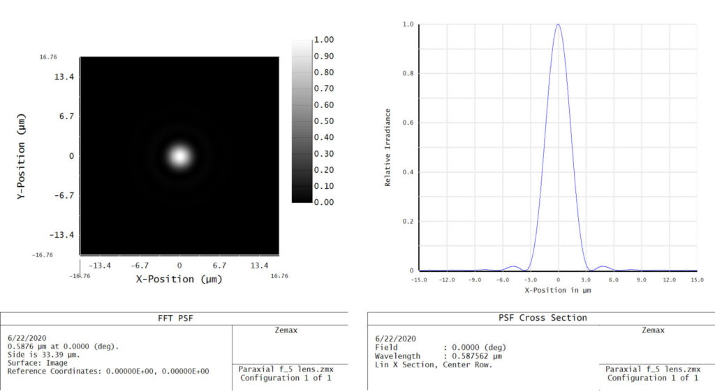
In the context of an imaging lens, encircled energy is a measure of the energy density of a focused spot. Consider an infinitely small emitting object (such as a star), and the lens under test forming an image of that object. The lens will necessarily aberrate the spot and create a point spread function (PSF)—a “perfect” lens forms an Airy disc.

Figure 1 – Airy Disc image from a perfect f/5 lens
The size of an airy disc is determined by the wavelength of light and the f/# (or numerical aperture) of the lens.

Figure 2 – Summing all pixels from the middle of point image outwards
Encircled energy is equivalent to summing all of the energy in the spot within a circle of a given radius. The radius of the circle is then increased to generate a plot of encircled energy vs. radius. An example is shown in Figure 3. We see that optical diffraction limits encircled energy. Aberrations will further degrade system performance.

Figure 3 – Point spread function vs. encircled energy for a perfect f/5 lens operating in the visible spectrum.
Extended Source Encircled Energy
Often the object of interest is not an infinitely small object. Consider a LIDAR scanner on an autonomous vehicle. The LIDAR transmission lens projects a spot with a non-zero diameter that may be resolvable to the optical system. The LIDAR receiver lens images that spot onto a detector—potentially an avalanche photodiode or SiPM detector.
The imaged spot size and encircled energy is no longer solely driven by optical diffraction or the diffraction limited point spread function (PSF). Geometric imaging of the resolvable spot now is the primary driver of encircled energy, with aberrations and diffraction further degrading performance (Figure 4).

Figure 4 – Extended source encircled energy for a perfect lens and a commercial doublet exhibiting modestly aberrated imaging. Both lenses are evaluated with a 200µrad angular source size.
Ensquared Energy
Detectors typically have square or rectangular pixels. Some designers prefer to use Ensquared Energy (also known as EE)to evaluate the signal collected by the square detector pixel. This is the same calculation as encircled energy, with a square analysis window instead of a circle. OpTest supports both measurements.
How OpTest® Software Measures Encircled Energy
Optikos products are ready to measure encircled energy “out of the box.” Install, align, and focus your lens as you would for any other measurement. Select a pinhole target and you’re ready to make measurements!

When making an encircled energy measurement the video image analyzer captures the image intensity distribution within a large square region centered on the image. OpTest 7 integrates the intensity within nested concentric circles (encircled) or square regions (ensquared) centered on the image and records these integrated intensities, normalized to the total enclosed energy in the region, as a function of radial location. OpTest 7 always calculates both encircled and ensquared measurements. There is no need to configure the test for just one measurement.

Figure 6 – OpTest 7 Sample Report – encircled energy (left) and ensquared
energy (right)
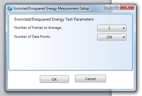
Because the tails of the image intensity may be very low within the selected region, the signal to noise may be improved by averaging multiple frames of image data, specified in the Number of Frames to Average drop-down box. The selected parameters apply at all field points at which the measurement is made.

Figure 7 – OpTest 7 encircled energy measurement setup window
Encircled Energy Requires a Pinhole Target
Encircled energy is a measure of the 2-dimensional energy density formed by a pinhole object. If a crosshair target is used only a 1-dimensional PSF can be generated. Crosshair targets “lose” information about lens aberrations in radial directions that do not align with the crosshair. You cannot make an accurate encircled energy measurement using a slit or crosshair target. All OpTest and LensCheck systems include pinhole targets.
Diffraction Encircled Energy vs. Extended Source Encircled Energy
OpTest enables both measurements—use a small pinhole to measure diffraction encircled energy. Use a large, resolvable, pinhole to measure extended source encircled energy. LensCheck and OpTest benches already include a range of pinhole targets to support both options. If you want to measure extended object encircled energy with a specific object size Optikos can provide customized pinhole targets. Contact Optikos to discuss further.
Encircled Energy Requires a Darkened Testing Environment
Because the encircled energy measurement integrates very low signal levels at the tails of an image it is critical that no light from the testing environment is present during the measurement. Ambient room lights may not be visible in the Live Video window but can still impact measurements, particularly for wide angle lenses.
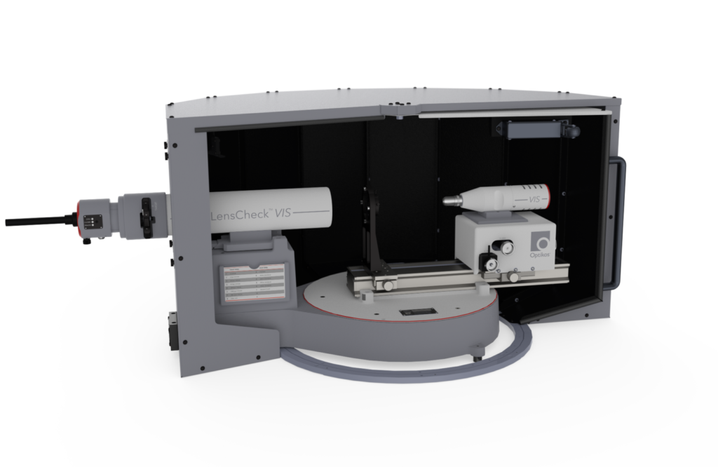
Optikos recommends testing in a darkened environment. Alternatively Optikos offers an optional LensCheck enclosure.

Figure 8 – Optional enclosure for LensCheck
Modulation Transfer Function and Encircled Energy are Not the Same!
For lenses specified in terms of encircled energy it may be tempting to use MTF as a test requirement. MTF and encircled energy are not correlated! Even at low spatial frequencies MTF cannot serve as a stand-in for accurate encircled energy measurements.
Below is a plot of MTF and extended source EE measurements for a population of 100 lenses. At an EE of 80% the MTF can vary anywhere from 30% to 90%! If a lens is designed for EE performance it is critical to use an instrument designed for this test.

Figure 9 – Test data from Optikos LensCheck of 100 lenses. MTF and EE are not correlated.
What Encircled Energy Is Not
Encircled energy does not measure lens transmission or coatings
EE does not account for losses through the lens due to bulk absorption or surface reflections that may arise from coatings (or lack thereof). EE is a measurement of energy density normalized to 100% regardless of the power losses in the optical system. Optikos offers a Transmission Kit ( see LensCheck options tab) to measure absolute lens transmission.
Encircled energy does not measure stray light
Two common measurements of stray light, Veiling Glare Index (VGI) and Glare Spread Function (GSF), are not accurately reflected in EE measurements. VGI requires out-of-field illumination. The EE measurement does not provide sufficient dynamic range for GSF. Optikos offers a VGI kit and GSF measurement in OpTest. See the Optikos white paper on Stray Light Measurement for more information.
Summary
Optikos is seeing increased interest in measuring encircled energy, particularly for LIDAR and other ranging/time-of-flight systems. Optikos has demonstrated that MTF is not an accurate figure of merit for these systems. Likewise, existing MTF benches that use slit and crosshair targets cannot produce accurate encircled energy measurements. Extended source encircled energy can be accurately measured with ONLY the LensCheck and OpTest metrology systems. Optikos products offer unparalleled accuracy and flexibility for characterizing all aspects of imaging lenses.
Get Started with Optikos
Optikos offers metrology products and services for measuring lenses and camera systems, as well as engineering design and manufacturing for optically-based product development. Our full-line of standard products for testing optical, imager and camera systems are appropriate for any industry and we will design a custom product for your specific application. Visit our website at optikos.com, email us at sales@optikos.com or give us a call at +1 617.354.7557 to learn more.


