Setting collimation is an alignment challenge faced by nearly every optics practitioner. There are a variety of methods for measuring collimation to guide this alignment process—some common ones are listed in Table 1. This table also identifies limitations associated with each method, which broadly fall into one of two categories:
- Source type restrictions
- Aperture size requirements of the metrology instrument

The scanning pentaprism stands out as the most versatile method by avoiding all of these limitations. Remarkably, it is also the lesser known technique, and consequently, no commercial instrument has historically been available. This led to the development and release of the Optikos ColliMeter™, which is based on the scanning pentaprism technique, to provide an objective means of measuring collimation for the widest variety of collimators. The ColliMeter™ introduces to this technique automated test routines and image analyses, as well as a portable architecture enabling collimator testing at point of use.
Let’s take a step back and discuss the concept behind the scanning pentaprism technique.
A beam of light is collimated if the rays in the beam are parallel to each other. When this is the case, a virtual image of the source has been projected such that it appears infinitely far away. Measuring collimation, then, requires subsampling bundles of rays in the beam and comparing each bundle’s propagation angle to that of the other bundles.
One way to accomplish this would be to translate an alignment telescope with a small aperture across the beam (Figure 1). Here we are leveraging the fact that the location of the image of the collimator’s source in the telescope’s camera frame is proportional to the angle of incidence of the ray bundle as it enters the telescope.

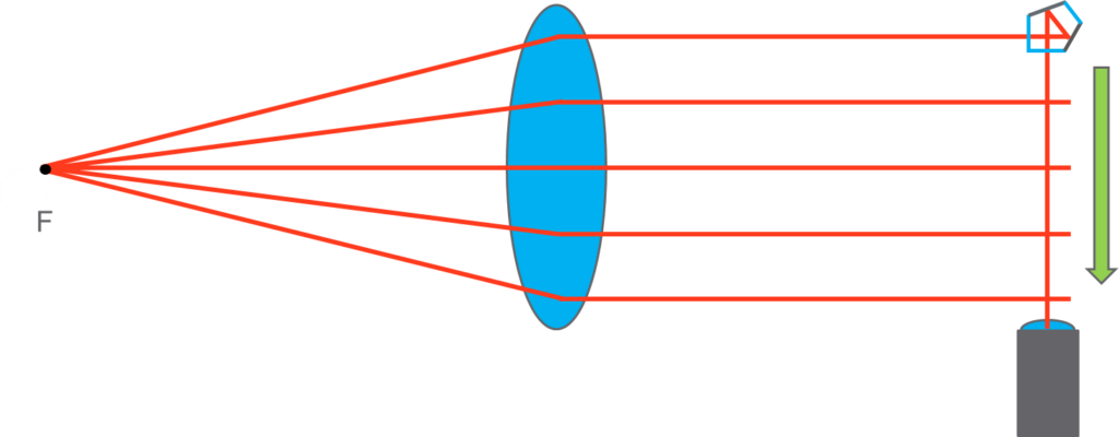
Since a tilt of the alignment telescope during the scanning motion would register as a false change in a ray bundle’s angle of incidence, the accuracy of this approach is limited by the straightness of the translation stage. A better approach is to rigidly fix the telescope to the collimator (or vice versa), and slide a pentaprism along the telescope’s line-of-sight, and across the collimator beam as in Figure 2.

A pentaprism deviates light rays 90° regardless of its rotation in the plane of this top-down view. This useful property decouples stage orientation from angle of incidence detection in this direction only. In our analysis, we will consider only beam deviations in this direction, and ignore the out-of-plane deviations. Because defocus is a rotationally symmetric aberration, it is valid to ignore the out-of-plane component of the image translation.
This is an elegant example of clever optical design enabling an instrument architecture that yields higher performance and lower cost than a state-of-the-art translation stage could provide!
The scanning pentaprism approach uses this layout to measure angle of incidence (image location) as a function of pupil position (pentaprism position). Optical designers might recognize the output as a transverse ray aberration curve, the slope of which is proportional to defocus.

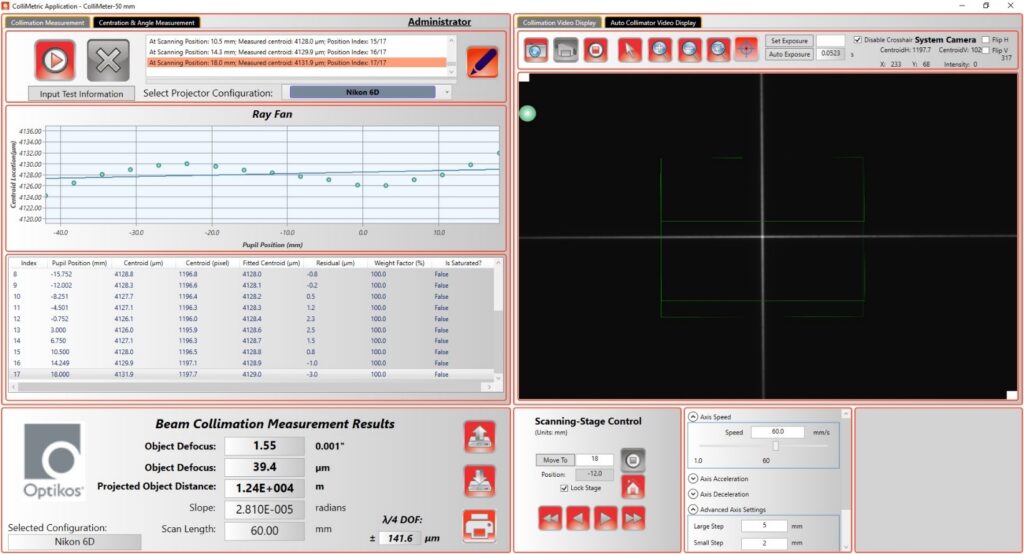
Now, let’s look at a practical case where we measure a common source of collimated light—the Nikon 6D Autocollimator.

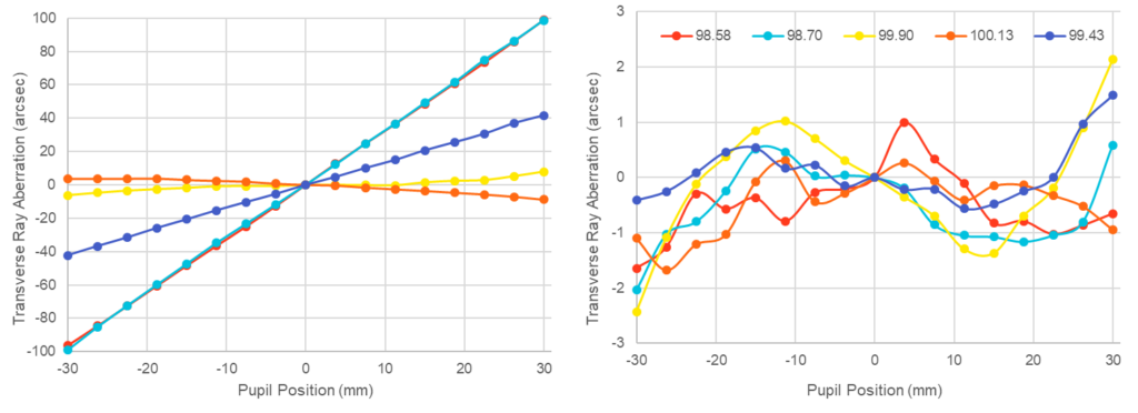
These workhorse alignment tools nominally project a collimated beam when the focus compensation ring on the nose of the autocollimator is set to its “100” graduation. With the ColliMeter™, we can measure residual defocus in the beam at this nominal setting (Figure 5a). Using the ColliMeter™ as feedback, we can also find the compensation ring setting which truly sets collimation (Figure 5b).

Following the above process, we are able to quickly and easily remove uncertainty in the focus setting of an every day tool at Optikos. The ColliMeter™ has also become the instrument of choice for aligning sources to off-axis paraboloid mirrors, focusing target projectors for camera testing, and even setting non-collimated beams to precise conjugates. A follow-up post showing the latter example will be published in the near future.
The ColliMeter™ is available now in two formats: the ColliMeter™ 350 VIS for collimators up to 350mm in diameter, and the ColliMeter™ 50, available in VIS and LWIR variants, which is a smaller benchtop unit for collimators up to 50mm in diameter. It’s a versatile tool designed from the hands-on measurement and qualification requirements of Optikos engineers that can provide a simple, objective numerical result to take the guesswork out of focusing.

