*Patent Pending
Introducing the New TM-1010 Thermal Module
The TM-1010 is the latest addition to the family of LensCheck™ and OpTest® Thermal Modules developed to enable lens testing over temperature, typically from -30° to +100°C. Specifically designed for small lenses with fields of view up to 160°, the TM-1010 adds to the range of automotive lenses that may now be characterized over a range of temperatures on a LensCheck instrument.

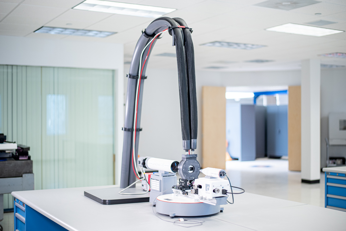
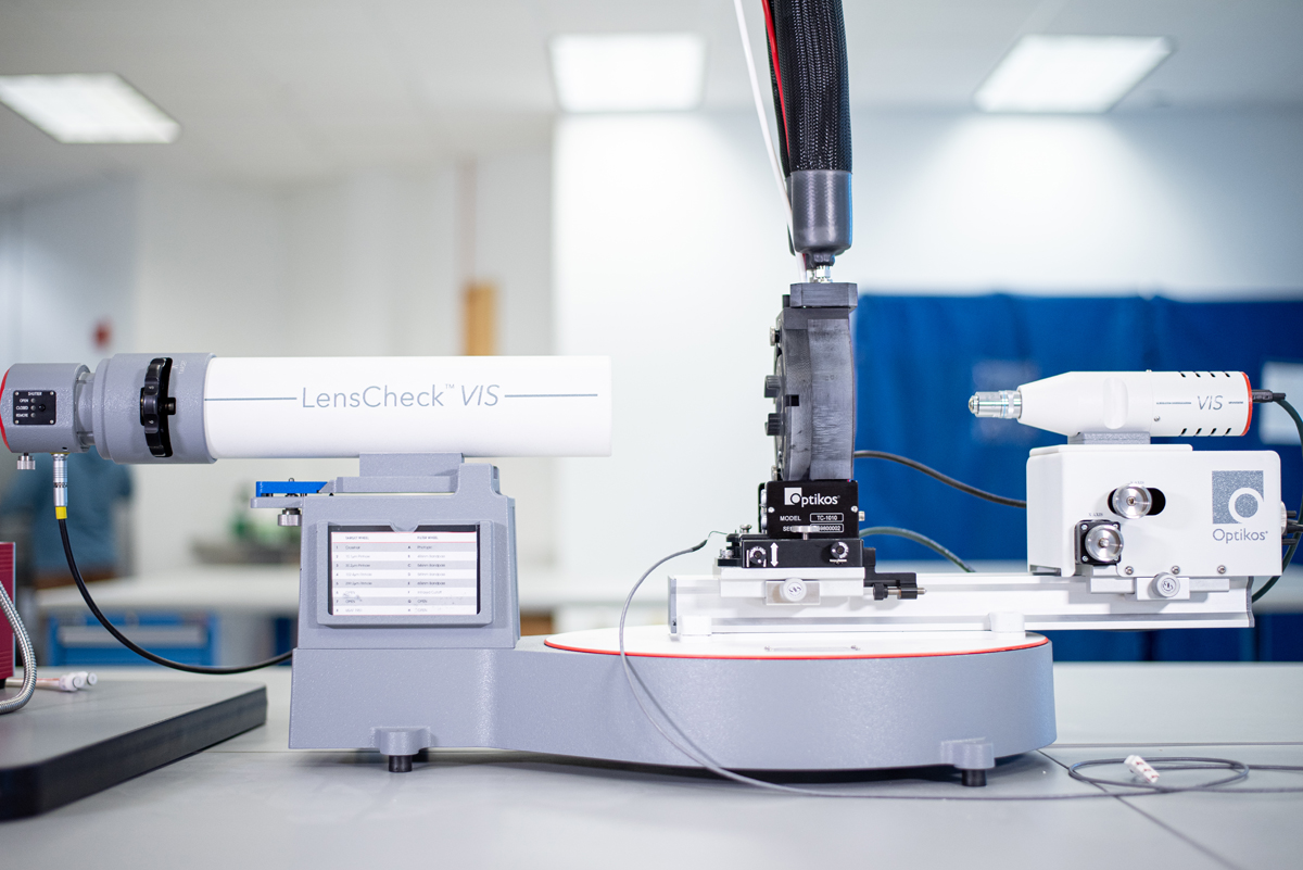
The TM Line of Thermal Modules is Patent Pending. The TM-1010 Thermal Module is shown mounted on the LensCheck™ System with skyhook.
Besides the thermal chamber in which the lens is mounted, thermal modules also include a recirculating thermal controller, a Skyhook™ hose carrier, and a dry air control manifold. Insulated hoses are provided to connect the three subsystems. The recirculating chiller/heater serves to control the temperature of the working fluid and to pump it through the walls of the heat exchanger in the thermal chamber. The manifold regulates the flow of dry air or nitrogen into the chamber, and the thermal chamber itself mounts either directly to the LensCheck™ instrument, or to the LP-1000 lens platform when used with an OpTest® system, and regulates the temperature of the lens under test. The design of the thermal chamber features an integrated tip-tilt mount to facilitate the alignment of the lens to the optical bench.
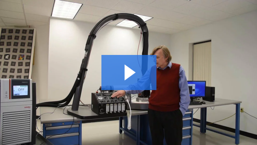
Watch Our TM-1010 Thermal Video Module Demo
Lens Performance is Sensitive to Temperature Changes
Temperature testing is particularly important for automotive lens manufacturers and integrators, whose applications have stringent performance and athermalization requirements to meet safety standards for camera image quality. The proliferation of these cameras brings with it the demand for lens testing over a wide range of temperatures. Optikos has refined techniques used to make these measurements for several years in our IQ-Lab as part of our ever expanding menu of measurement services. We are now pleased to offer the TM line of Thermal Modules* for Lens Measurements as accessories to our flagship OpTest® lens testing systems. As a newly introduced product line, all specifications in this data sheet should be considered preliminary and subject to change.
OpTest® Thermal Modules* Provide Measurements for a Range of Temperatures and Lens Shapes and Sizes
For more information about our temperature testing services, contact IQLab@optikos.com or complete our questionnaire.
Typically, there are two lens parameters that are of interest when making temperature dependent measurements: image quality, and flange focal length (FFL), the distance from the mounting flange of the lens to the image plane. The question of image quality is answered by finding the plane of best focus and then measuring the Modulation Transfer Function (MTF) of the lens in this plane. The flange focal length is the distance measured from this plane of best focus to the mounting flange of the lens. As discussed in more detail later, the approach taken here is to measure the temperature variation in FFL, not necessarily the FFL itself.
Designers of lenses to be used in automotive applications, in general, will design the camera system to be athermal, meaning that the image will remain focused on the sensor as the temperature of the lens changes. This does not necessarily mean that the distance from the mounting flange to the image plane of the lens measured in isolation is invariant with temperature! If the lens flange is mounted to the sensor with a non-negligible thickness of aluminum, for example, then an athermal lens design for this camera would require the FFL variation to actually track the thickness change in aluminum over the prescribed temperature range.
The OpTest® TM Thermal Module is used in place of the usual lens mount on the LP-1000 lens platform of an OpTest bench equipped with a visible image analyzer, such as the VI-1000, and enables an operator to measure both image quality and flange focal length.
System Components
There are three main components to the TM system: the recirculating chiller/heater, the manifold, and the thermal chamber in which the lens is mounted. Insulated hoses are provided to connect the three subsystems. The recirculating chiller/heater serves to control the temperature of the working fluid and to pump it through the walls of the heat exchanger in the thermal chamber. The manifold regulates the flow of dry air or nitrogen into the chamber, and the thermal chamber itself mounts to the LP-1000 lens platform and regulates the temperature of the lens under test. The design of the thermal chamber features an integrated tip-tilt mount to facilitate the alignment of the lens to the optical bench.
TM Thermal Chamber Use and Design Considerations
In order to make measurements across the field of view of the lens, it is generally preferable to place the front of the lens under test close to the chamber window. This mitigates the effect of the chamber aperture vignetting the incident beam at steep off-axis angles. The problem of achieving this condition for lenses of different lengths is solved through the innovative design of an expandable heat exchanger.
Segments may be added to, or removed from the cell in order to match the chamber length to that of the lens under test. Each added segment includes an outer ring of rigid insulation and an inner heat exchanger section that incorporates sectors of spiral channels for the working fluid, thereby ensuring thermal uniformity as the fluid circulates through the entire length of the cell along a double helix path. The light input end of the heat exchanger stack is enclosed by a double glazed window section consisting of a pair of air-spaced precision fused silica windows for improved thermal insulation, and at the other end of the stack is the lens mount, discussed in more detail below.
Dry air or nitrogen passes through the heat sink and is introduced into the thermal chamber at the window end. It then flows over the lens under test and exits at the image side of the chamber. No window is present on the image side of the lens because including one would introduce spherical aberration into the image. The exception to this rule is the case in which a window of appropriate thickness is required in order to simulate the effects of cover glass over the sensor.
When the lens is cooled below the ambient dew point, exposing it to the room air will result in condensation or frosting on the last optical surface. During measurements, a low flow of dry nitrogen or air over the lens maintains positive pressure in the cell and prevents this effect. Between measurements, an increased flow rate of dry gas over the lens helps accelerate temperature changes by providing a forced convection heat transfer path in addition to conduction through the lens mount.
A motorized thermal shutter is incorporated at the image side of the chamber. The shutter serves to close off the end of the chamber until the lens has reached thermal equilibrium, at which point it automatically opens only for the time required to make a measurement. The shutter blades are magnetically attached and can be easily removed to provide full access to the interior when inserting or removing the lens.
The temperature of the lens is monitored continuously using one or more platinum resistance thermometer probes affixed directly to the lens housing.
Lens Mounts
The lens mount serves two important roles: it is the primary thermal conduction path from the heat exchanger to the lens under test; and it provides the reference surface for flange focal length measurements. It consists of two parts—the carrier and the insert. The carrier is provided with the Thermal Module and interfaces directly to the end of the heat exchanger. The insert, often designed and provided by the customer, mounts the lens under test and interfaces to the carrier. When the flange focal length variation of the lens needs to be measured, it is typical to fabricate the insert from a low expansion alloy (such as Invar) so that the side nearest the image analyzer may be used as a proxy reference for the flange itself.
At each temperature point the image analyzer microscope is focused on the near surface of the insert and then again at the image plane of the lens, and the distance between the two is recorded. Since this dimension includes the thickness of the insert, this is not the flange focal length, but has the same thermal variation since we assume changes in the Invar thickness to be negligibly small. The insert may also be designed to carry the actual structure or housing used for mounting the lens to the sensor in the camera, in which case the rear surface of the mount may be used as a reference by the image analyzer.
Models
The Thermal Module line currently consists of three models, the TM-1150 with a heat exchanger internal diameter of 150mm, and the TM-1050 with an internal diameter of 100mm, and the TM-1010. The TM-1010 is intended for small lenses with fields of view up to 160°.The TM-1050 is intended for testing relatively small imaging automotive camera lenses, while the TM-1150 is used for measuring larger LIDAR type lenses and imaging lenses mounted in large housings or with large windows attached.
All three models use the same recirculating chiller/heater and manifold, and both models are designed to be compatible with the OpTest LP-1000 lens platform. Although very small lenses can be measured in the larger chamber, it is generally true that, because of its lower thermal mass, the TM-1010 and TM-1050 will heat and cool more rapidly than the TM-1150. Also, because of its smaller surface area, heat losses are somewhat less in the smaller chamber enabling it to reach lower temperatures.
OPTEST® THERMAL CHAMBER SPECIFICATIONS* |
|||
| Model | TM-1010 | TM-1050 | TM-1150 |
| Compatible Test Bench | OpTest® Lens Testing Bench* and LensCheck™ | OpTest® Lens Testing Bench* and LensCheck™ | OpTest® Lens Testing Bench |
| Compatible Wavelength Range | Visible-NIR. Compatible with VI-1000 image analyzers and LensCheck Image Analyzer | Visible-NIR. Compatible with VI-1000 image analyzers and LensCheck Image Analyzer | Visible-NIR. Compatible with VI-1000 image analyzers |
| Maximum Allowable Lens Diameter | 10mm† | 50mm† | 150mm† |
| Maximum Allowable Lens Length | 10mm† | 30mm† | Chamber length can be increased with additional segments. Contact Optikos for more details. |
| Maximum Allowable Entrance Pupil Diameter | Contact Optikos for more details. | 45mm | 95mm |
| Chamber Segment Width | N/A (Chamber has fixed depth) | N/A (Chamber has fixed depth) | 15mm |
| External chiller/heater | Julabo Presto A40 OR Julabo Presto A80 |
Julabo Presto A40 OR Julabo Presto A80 |
Julabo Presto A40 OR Julabo Presto A80 |
| Ambient Temperature | 10°C to 30°C | 10°C to 30°C | 10°C to 30°C |
| Working fluid | Galden HT-135 thermal fluid (not provided with system) | Galden HT-135 thermal fluid (not provided with system) | Galden HT-135 thermal fluid (not provided with system) |
| Power Requirements | 208V/60Hz/15A (US)
(International options available) |
208V/60Hz/15A (US)
(International options available) |
208V/60Hz/15A (US)
(International options available) |
| Maximum Attainable Lens Under Test Temperature | 105°C | 105°C | 105°C |
| Minimum Attainable Lens Under Test Temperature | With A40: -30°C typical With A80: -40°C typical |
With A40: -25°C typical With A80: -40°C typical |
With A40: -10°C typical With A80: -30°C typical |
* Adapter Required
† Even when smaller than these dimensions, lens geometry and test bench may reduce the number of possible measurements over temperature. Contact Optikos with your specific lens details for guidance on which chamber best suits your application.


